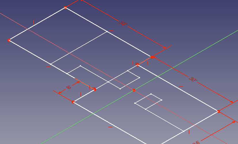
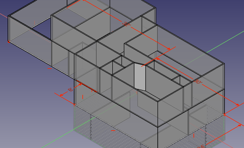
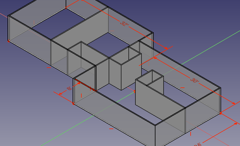
The Arch Wall Command adds a wall object to your model. If a qualifying entity is selected ( wire, edge, line ) the wall command will construct the wall based on this entity.
This article shows the wall for American Residential, however, the focus is on qualifying edges and in this regard is useful for industrial understanding as well.
Check the Defaults
In Preferences we can set defaults for the Arch workbench. Specifically for walls, we can set the Width, Height and Color. Although Arch can use Imperial measurements the preferences dialog only accepts metric. Here I have set my defaults to be 3.5″ and 8 ft.
Wall Default

Create a Wall
The wall uses an edge as it’s input. You can select any edge. If it is a closed edge it should not have a face.
with a Sketch
Sketches provide valid edges for a wall and provide some advantages.
- Layout is more intuitive than Draft Lines
- Measurements can be applied visually
- Changes get updated in wall object.
- Entire floor plan can be contained in a single sketch ( and named )
- This Floorplan can be easily sent to TechDraw Workbench
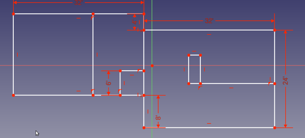
To create a wall from this sketch you simply select the sketch ( or an edge of the sketch ) and click the Wall tool from Arch workbench.
There are also some issues ( at the time of publish )
- Some edges may get excluded.
Current Strategy
Create exterior walls in a single sketch using Poly tool. IT is not necessary to use Part Design WorkBench.
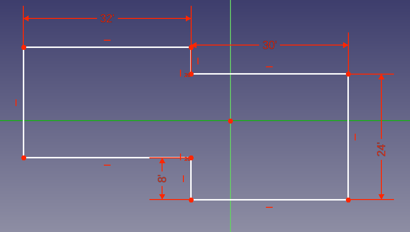
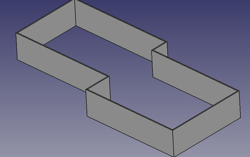
Then add internal walls, use link to external geometry to make sure the internal wall intersect nicely with the exterior walls.
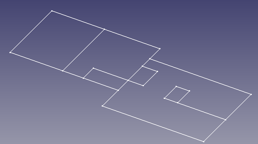
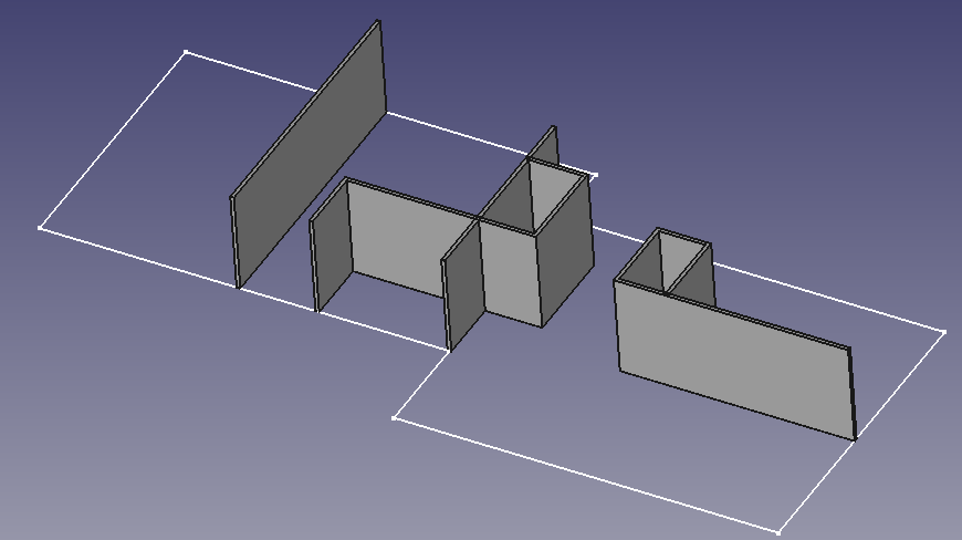
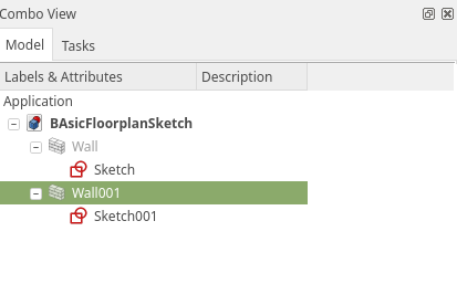
Adding a second floor
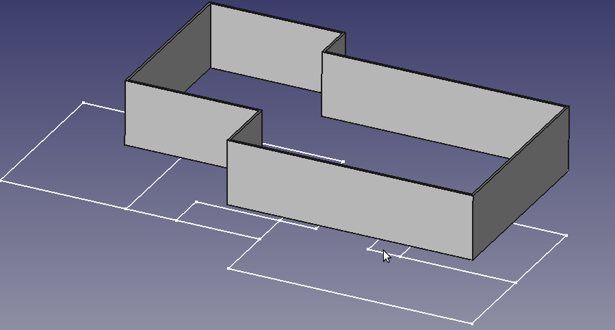
Use the same exterior wall strategy as the first floor, but we will set the Z position of the sketch at 8′. If the layout calls for it it is a simple matter to use “External Geometries” in the sketch to layout the second floor walls.
NOTE: Later when we use the Floor Container, we can remove the sketch Z height.
Additional add internal walls as prescribed. Use a second sketch
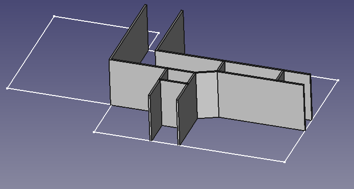
Remember to set the Z position of the Interior walls to 8′
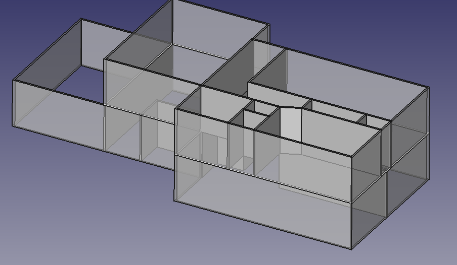
If we set the exterior walls transparency to 50 we can get a nicer visual.
A “Basement”
With an Exterior wall and Interior walls set to -8 ft on the Sketches Z Position. We will need to change the thickness/width of the walls.
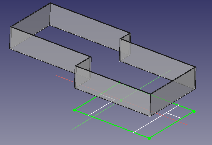
Creating the wall and adding Blocks.
As basement walls generally tend to be cinder-block or cement. We don’t want an intersection of the interior walls into the basement.
To make Rendered blocks transparent, it helps to set the Line andPoint colors to a softer color, to help them blend in a bit. With transpancy set to 50%, the outlines of the blocks become overwhelmine. If we set the lines and points to grey we get a better visual.
WARNING: Showing the Blocks significantly affects performance, it is a good idea to leave blocks off while modeling.
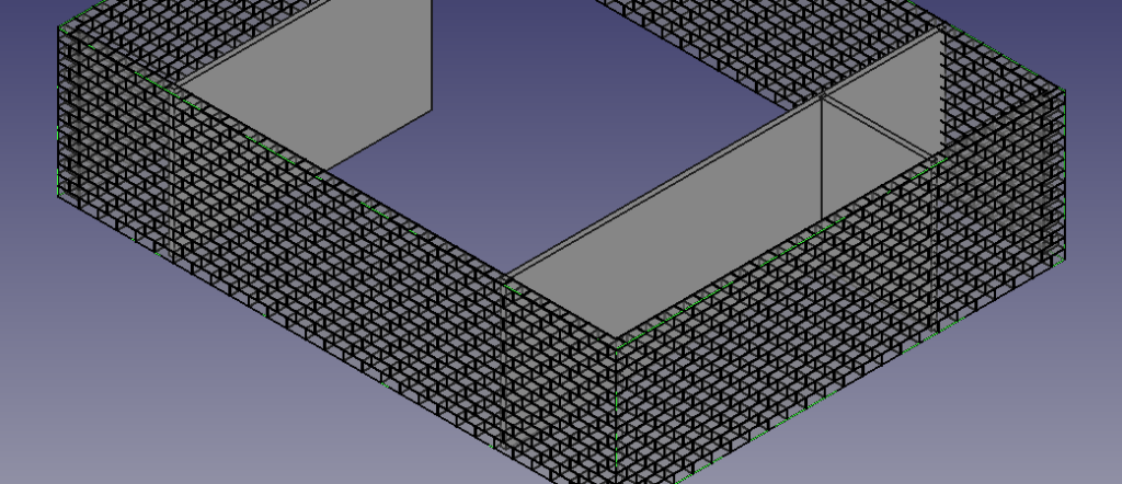
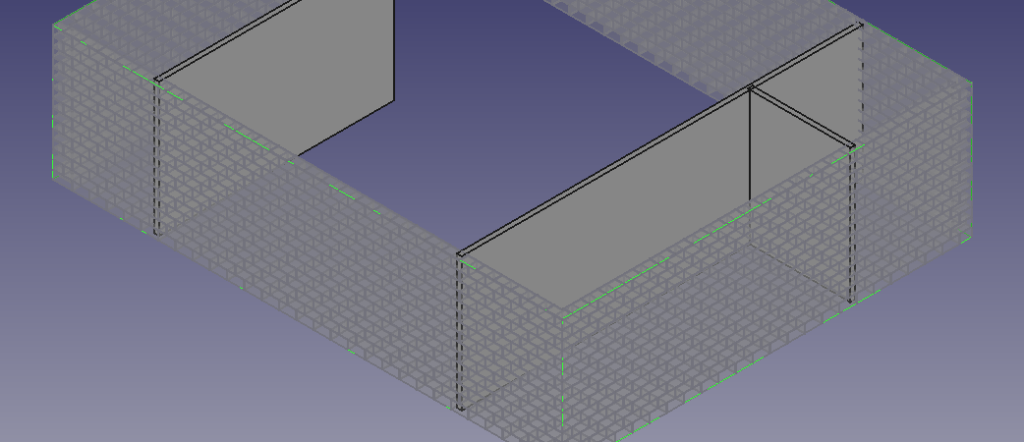
Wall Properties
Alignment
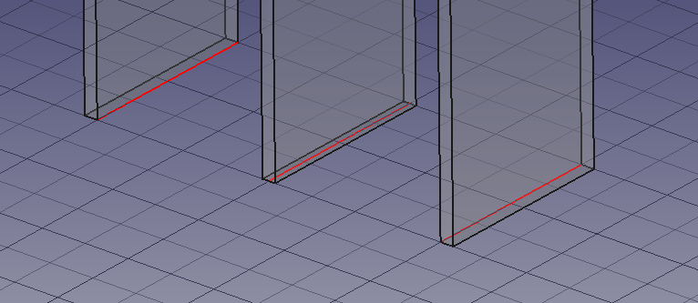
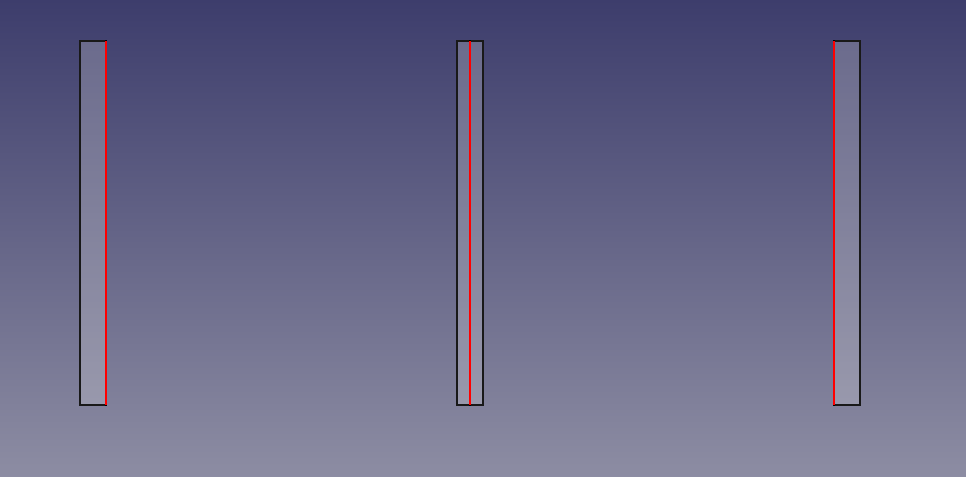
-Refers to how the wall is built up around the edge. The figures below show three walls and the edges from which they are constructed. A left alignment means the wall sits to the left of the line. Pictured below shows alignments in order Left, Center, Right
Height, Length and Width
Provide basic dimensions of the wall. Length is not used when the wall is based on an edge it is a display/read only value ( seems to be broken currently) .
Offset
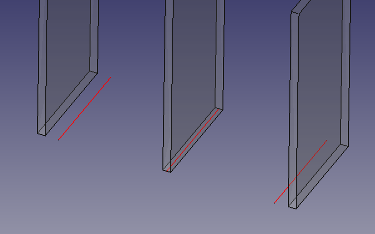
Will position the wall the given distance from the edge by which it was constructed.
Component Properties
Calculated Values
- Horizontal Area – Amount of square area the wall will sit upon
- Vertical Area – A sum of the areas of all the faces
- Perimeter Length – The perimeter of a qualified wall. It seems walls that form a closed loop will calculate a perimeter.
Linked Objects
- Base – The geometry/object this wall is based on.
- Clone Of – the wall this wall is a clone of.
- Material – material used to construct this object.
- Subtractions – Items removed from this wall, like Windows and Doors.
Blocks
Indivual Blocks
Block Height, Block Length – Determine the Face dimensions of the block. Block width is determined by the wall width.
Block Layout
- Offset First – Create an offset of the first Block/Row to implement an overlap for structural strength
- Offset Second – Create and offset of the second Row for additian overlap
Joint
The mortar joint can be defined by thickness as needed
Calculated values – used for Materials List / BIM
- Count Broken – The number of blocks that will need to be cut
- Count Entire – The number of necessary Blocks.
