The Subtractive Groove uses a Sketch to remove material from a Body. The selected sketch is rotated around an axis and removes material that it intersects. To complete a successful groove it must intersect some parts of the Body in which it is contained.
If you prefer to watch a video:
Creating a Groove
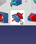
To create the groove we will re-create the Icon shown in the toolbar. Sans, the colors and the red line in the middle.
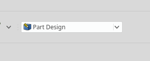
Create a New Document, Select Part Design and add Body
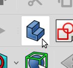
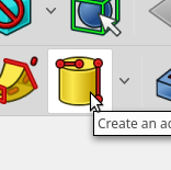
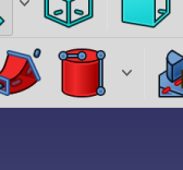
Select an additive cylinder
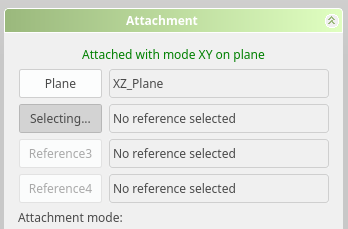
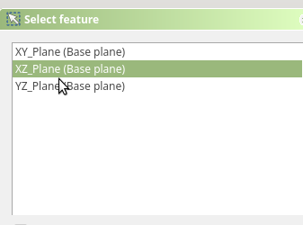
Pick the XZ-Plane as its attachment
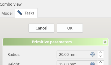
- Set the Cylinder radius to 10.00 mm
- Set the Height to 25.00
- Set the Angle to 90 Degrees
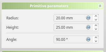
Click OK to accept the cylinder.
- Subtract the middle with a subtractive cylinder
- Select the subtractive cylinder
- Pick the XZ-Plane as its attachment
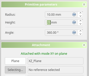
- Set cylinder radius to 10.00 mm
- Set the height to 25 mm
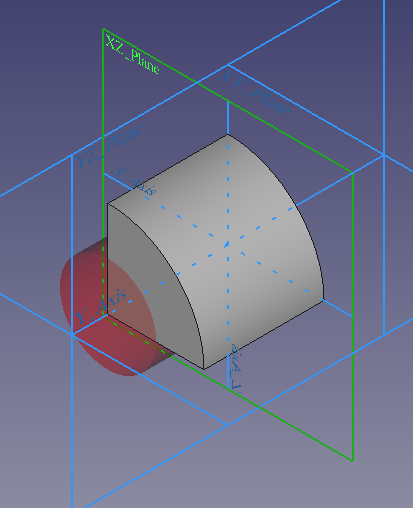
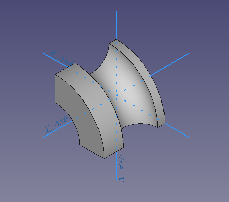
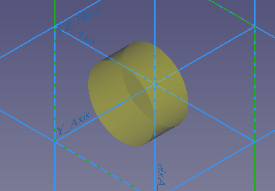
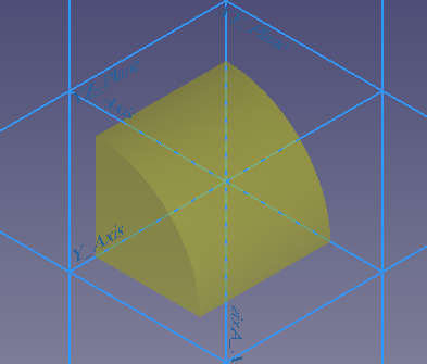
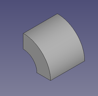
Our basic body is complete:
Add a sketch
Attach to XY-Plane
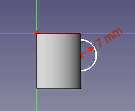
Add a Circle
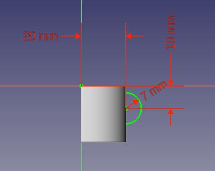
Constrain the circle radius to 7 mm
Use a Horizontal contraint from the Circle center to the Sketch Origin, set te distance to 20
Use a Horizontal contraint from the Circle center to the Sketch Origin, set te distance to 10
Add the Groove
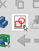
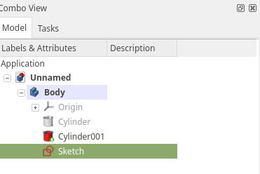
Select the Sketch in the Model Tree and Select the Create a Groove tool
Select the base Y-Axis as the revolution axis.
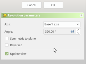
The Groove will be added and you can click OK to accept your choice