
The “Draft on Face” tool is similar to a chamfer. Some of the differences are in how it is constructed. The Draft is applied to a single face and the value input is degrees. This makes it more useful for certain operations ( like carpentry ) where the angle is known and not the length of the cut.
Notice: I have created this tutorial only with the knowledge I learned from getting a good result. This was intentional so that I don’t use any “expert-speak.” As a result, there are some pieces missing as I have not determined exactly how they work or a good way to explain them.
You can watch a Video version of this tutorial here:
Creating a Simple Draft.
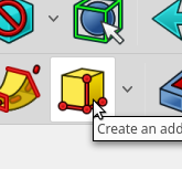
To create a “Draft” on face begin with a box. We can use the additive box with it’s default settings. Click the Additive Primitive and select Additive Cube.
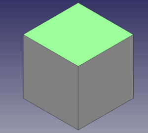
Select the face to which you would like to apply the draft. ( This requires a pre-selected face ).
Select the Add a Draft Tool.
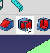
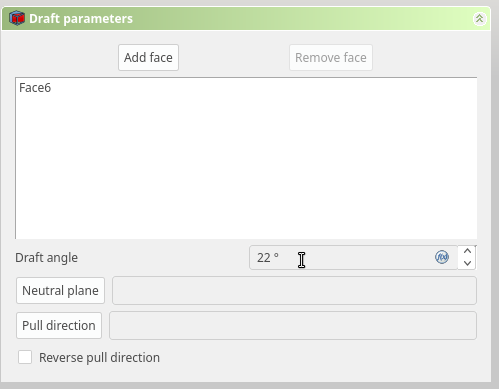
Once selected the “Tasks Tab” Will be updated with the “Draft Parameters” dialog.
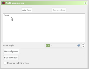
You will notice the face you selected is listed. You can add additional faces to apply the Draft to by clicking “Add face”
For our example we will be adding a large draft to make the example obvious. Set the draft angle to 22 Degrees
The Additive Cube should be update as you type and you will see the Cube with the new draft.
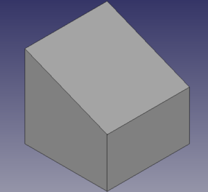
That’s all you have to do to create a Basic Draft. It can however get more dicey when you add complexity.
Some Notes on Errors
If the Angle you select results in a valid Draft it will be updated in your Document window. If you select and angle that results in the adjacent face being removed, the draft will fail.
If the draft is invalid, you will see a red status error in the status bar.
The Draft does not fail gracefully. This means that the problem can be non-obvious. The problem is shown in the status bar and recorded in the Report view.

Reverse Pull Direction
By default the Pull direction is in the “Z Axis” of the plane selected. You can think of it as pulling in, or pulling out. ( Note: This is technically called the “Normal” of the face. )
Default “Pulled-In”, or pulled in the -Z direction of the face.
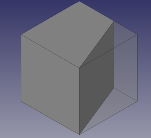
Reverse Selected, or “Pulled-Out” in the Z Direction of the face.
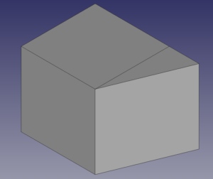
The Neutral Plane
The Neutral Plane is a single plane on the object being drafted that will not be resized. You can use this plane to orient the draft.
Without technical details, the best I can determine, is the default neutral plane is placed on the 1st edge of the plane. So if the plane is a square and has edges Zero to Three, the neutral plane will be the plane adjacent to the 1st edge. But I could be wrong.
The Draft starts at the neutral plane and moves away from it. Consider the two cubes. The first has the default neutral plane the second has the Top of the cube selected.
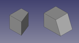
Selecting a Neutral plane that is non-adjacent will result in no Draft
Understanding the Neutral Pane
Here are four Drafts, the selected Draft Face is on the Top, the leftmost cube is the default draft. The Neutral Plane is shown in green. Notice in some cases the Draft is pulled away from the cube. The origin for the cube is indicated by the Arrow.

Changing the Neutral Plane can reverse the Pull Direction. When you change to Neutral Plane the Pull Direction is in reference to the first edge.
Selecting a Pull Direction Edge.

It is possible to create a custom pull direction. When I get it to work in a reliable, understandable fashion I will update this post.