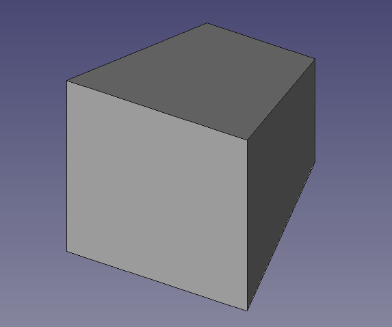
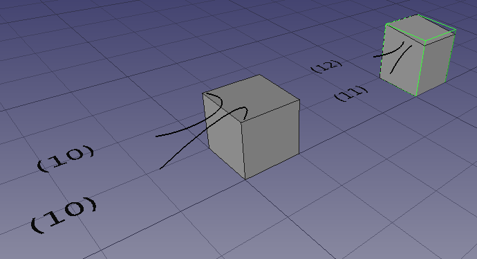
The Wedge is a “Parametrized Geometric Primitive” Using 9 parameters to define the orientation of all 6 sides of the wedge.
You can find the official documentation here:
https://wiki.freecadweb.org/Part_Wedge
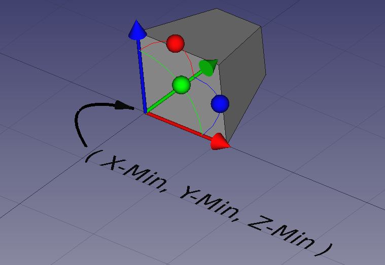
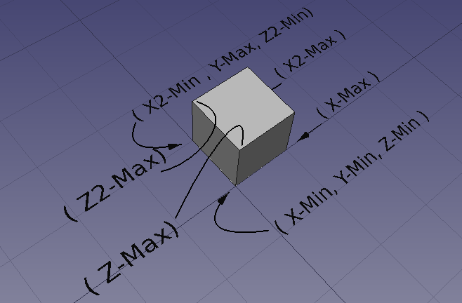
In this explanation the parameters will be be in regard to a vertex they effect. These parameters are in actuality used to define to position of the face. However, it seems easier to keep track of the vertices that define the plane.
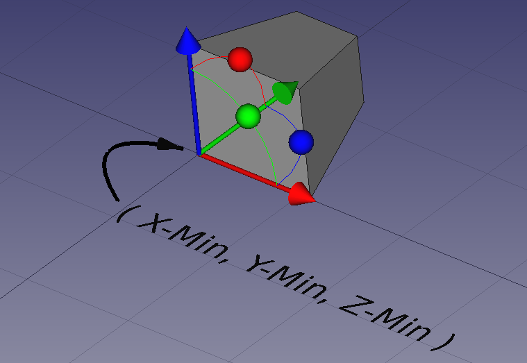
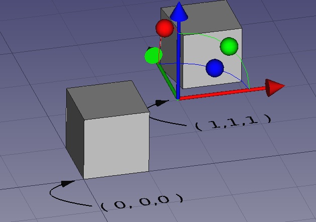
Starting with the Origin of the wedge changing X-min, Y-Min, and Z-min from ( 0,0,0) to (1,1,1) moves the origin vertex. Notice it does not move the wedge but changes the wedge geometry. The “Local Origin” remains at 0,0,0
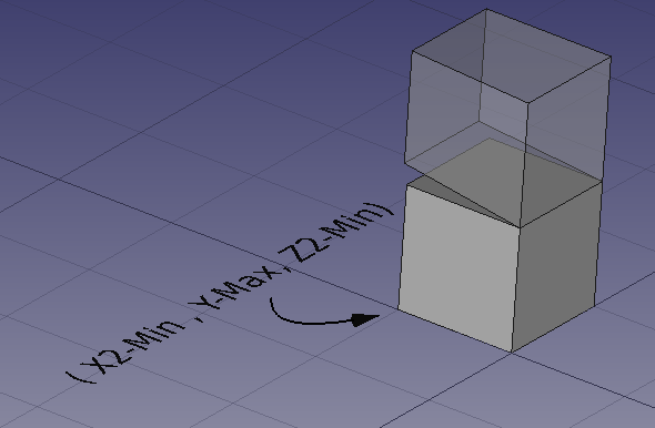
x2-min, Y-Max, Z2-Min
In This scenario we will modify the X2-Min, Y-Max, Z2-Min set of parameters. The set of parameters re-orients the lower X-Y plane and resizes the 3 sides as needed.
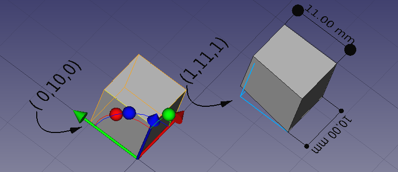
Changing parameter from 0,10,0 to 1,11,0 results in the following:
Note the orientation of the initial wedge, it’s orientation has not been modified. It is located globally at 0,0,0 and all axis are the same as the global axis.
The second figure shows the two wedges stacked to demonstrate the effect on the lower X-Y Plane
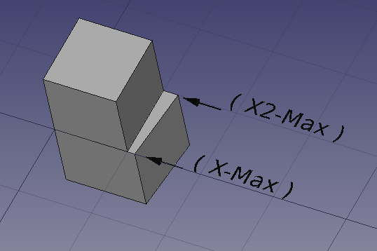
Increasing X-Max and X2-Max each by one.
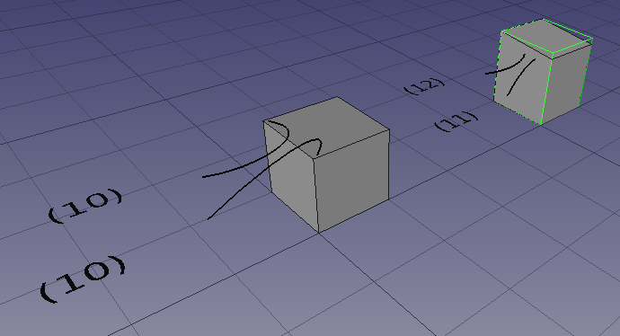
Increasing the X-Max values will adjust the higher order Y-Z plane. Consider the following wedges. Each figure shows an unaltered 10x10x10 wedge ( basically a cube ) and a wedge with X-Max and X2-Max increased by 1 an 2 respectively.
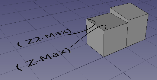
Increasing Z-Max and Z2-Max each by one.
Finally we can treat the two Z-Max and Z2-Mac the same way showing an increase of 1mm and 2mm respectively.
This final figure has all the “min” values increased by 2 on the far end and 4 on the closer end. All the “Max” values reduced by 2 on the fare end and reduced by 4 on the near end.
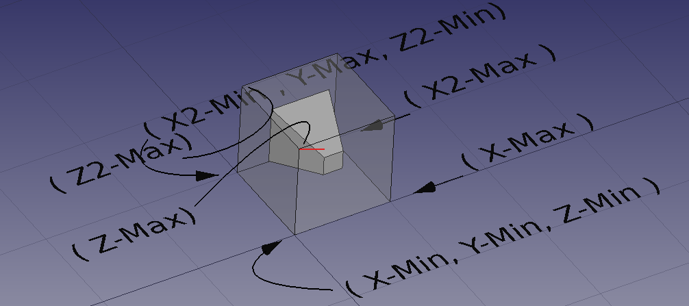
This is my first pass at making the Wedge easier to understand. I do not think I have succeeded. I will try again in the future.
